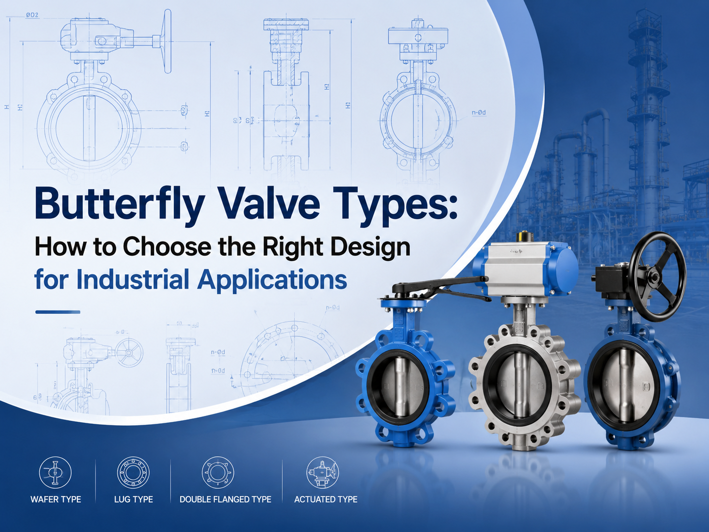
Основные типы поворотных дисковых затворов включают концентрические, с двойным эксцентриситетом, с тройным эксцентриситетом, межфланцевые, с проушинами, фланцевые, с мягким уплотнением, с металлическим уплотнением, ручные, пневматические и электрические поворотные дисковые затворы. Правильный выбор зависит от давления, температуры, рабочей среды, требований к герметичности, монтажного пространства и частоты эксплуатации. Какие бывают основные типы поворотных дисковых затворов? Поворотные дисковые затворы обычно классифицируются по конструкции диска, типу соединения корпуса, материалу седла и способу привода. Эта классификация важна, поскольку два затвора могут называться поворотными дисковыми затворами, но их эксплуатационные ограничения могут сильно отличаться. Поворотный дисковый затвор использует вращающийся диск для перекрытия или регулирования потока. Благодаря компактной конструкции, малому весу и четвертьоборотному управлению он широко применяется в водоочистке, электростанциях, химической промышленности, системах HVAC, морских системах и общепромышленных трубопроводах. Для покупателей ключевой вопрос не просто «какой тип дешевле?», а «какой тип сможет выдержать фактическое давление, температуру, рабочую среду и требования к уплотнению?» Концентрический поворотный дисковый затвор A концентрический поворотный дисковый затворимеет шток, расположенный на осевой линии корпуса затвора и диска. Его также называют поворотным дисковым затвором с центральной осью. Этот тип обычно используется для применений с низким давлением и общего назначения, особенно с водой, воздухом и неагрессивными жидкостями. Он прост, экономичен и удобен в обслуживании. Ограничением является износ седла. Во время открытия и закрытия диск остается в контакте с мягким седлом на протяжении значительной части движения. Для более высокого давления, более высокой температуры или более строгих требований к перекрытию потока конструкции с двойным или тройным эксцентриситетом часто подходят лучше. Поворотный дисковый затвор с двойным эксцентриситетом A поворотный дисковый затвор с двойным эксцентриситетомиспользует два эксцентриситета для снижения трения между диском и седлом. Это улучшает герметичность и помогает продлить срок службы по сравнению с базовой концентрической конструкцией. Поворотные дисковые затворы с двойным эксцентриситетом часто выбирают для промышленного применения со средним давлением, включая нефтегазовую отрасль, водоснабжение, производство электроэнергии и химические системы. Они полезны, когда требуется повышенная долговечность, но не нужна полностью металлическая конструкция с тройным эксцентриситетом. Этот тип также часто называют высокоэффективным поворотным дисковым затвором. Перед выбором покупатели должны проверить класс давления, материал седла, конструкцию уплотнения вала и ожидаемую частоту эксплуатации. Поворотный дисковый затвор с тройным эксцентриситетом A поворотный дисковый затвор с тройным эксцентриситетомдобавляет т...
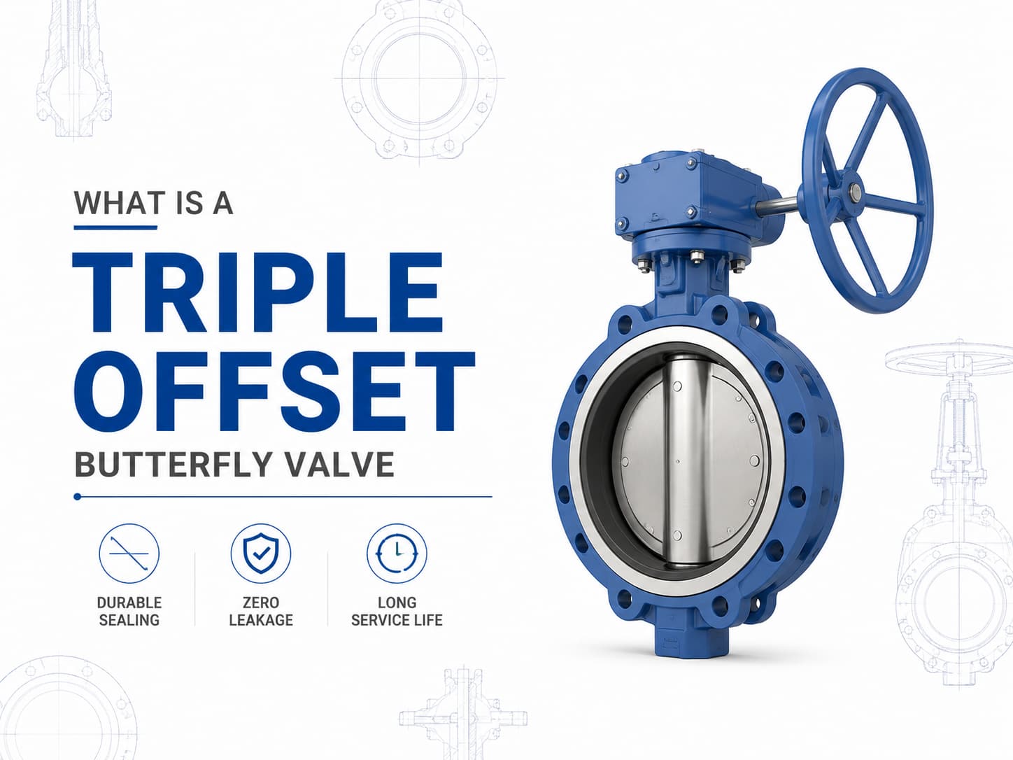
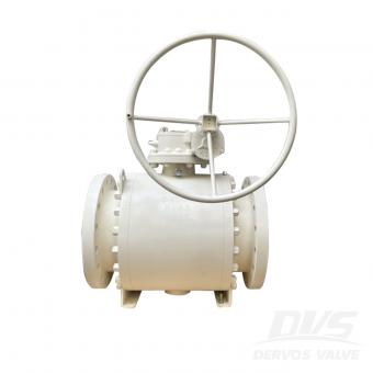
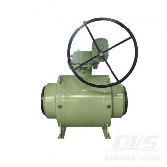
A трёхэксцентриковый поворотный затвор представляет собой высокоэффективный запорный клапан, предназначенный для применений, где обычные поворотные затворы с эластичным уплотнением или с двойным эксцентриситетом не могут обеспечить требования по давлению, температуре или герметичности. Благодаря использованию конструкции уплотнения с тремя эксцентриситетами клапан обеспечивает механизм металлического уплотнения с уменьшенным трением между диском и седлом во время работы, что делает его подходящим для сложных условий эксплуатации, таких как нефтегазовая промышленность, нефтехимия, энергетика, СПГ, паровые и промышленные технологические системы. Конструкция и принцип работы трёхэксцентрикового поворотного затвора В отличие от концентрического поворотного затвора, где вал расположен на центральной линии диска и седла, трёхэксцентриковый поворотный затвор имеет три независимых геометрических эксцентриситета. Первый эксцентриситет смещает вал относительно центральной линии корпуса клапана, второй эксцентриситет смещает вал относительно центральной линии трубопровода, а третий эксцентриситет вводит коническую поверхность уплотнения вместо круглого профиля уплотнения. Такая геометрия позволяет диску сразу отходить от седла после начала вращения, устраняя трение между уплотняющими поверхностями. Главное преимущество этой конструкции заключается в том, что усилие уплотнения создаётся крутящим моментом, а не постоянным сжатием мягких материалов. Если применение требует работы при высокой температуре, то металлический трёхэксцентриковый поворотный затвор часто является предпочтительным выбором, поскольку эластомерные седла могут разрушаться при повышенных температурах. Если среда содержит абразивные частицы или агрессивные химические вещества, то выбор материалов для диска, седла и корпуса становится критически важным для предотвращения эрозии, коррозии и утечек при длительной эксплуатации. Стандарты и материалы трёхэксцентрикового поворотного затвора Трёхэксцентриковый поворотный затвор обычно изготавливается в соответствии с такими стандартами, как API 609, EN 593 и ISO 5752, с номинальными классами давления от Class 150 до Class 600 и выше в зависимости от требований конструкции. Типичные материалы включают углеродистую сталь, нержавеющую сталь, дуплексную нержавеющую сталь, алюминиевую бронзу и сплавы на основе никеля. Для применения в агрессивной морской воде могут использоваться алюминиевые бронзы, такие как C95500 или C95800, тогда как для работы в условиях воздействия сернистых сред могут потребоваться материалы, соответствующие требованиям NACE MR0175/ISO 15156. Герметичность и контроль утечек трёхэксцентрикового поворотного затвора Герметичность трёхэксцентрикового поворотного затвора зависит от взаимодействия между уплотнительным кольцом, качеством обработки поверхности седла, рабочим крутящим моментом и совместимостью материалов. Поскольку уплотняющие поверхности соприкасаются только в конечном положении закрытия, механический изно...
Шаровые краны и пробковые краны — это поворотные клапаны с четвертьоборотным управлением, используемые для включения-выключения и изоляции в промышленных трубопроводных системах. Хотя они имеют схожие принципы работы, их внутренние конструкции приводят к различным эксплуатационным характеристикам, особенно с точки зрения герметичности, способности выдерживать давление, рабочего крутящего момента, требований к техническому обслуживанию и пригодности для различных сред. Выбор между шаровым краном и пробковым краном должен основываться на фактических условиях эксплуатации, а не на предпочтении определенного типа клапана. Если применение требует надежного перекрытия потока, частого срабатывания и низкого рабочего крутящего момента, часто предпочитают шаровой кран. Если система работает с загрязненными средами, абразивными частицами или большими проходными сечениями, пробковый кран может обеспечить более высокую надежность. Конструктивные различия и характеристики герметизации A шаровой краниспользует сферический запорный элемент с просверленным проходным отверстием. Когда клапан открыт, отверстие совмещается с трубопроводом, обеспечивая практически неограниченный путь потока. При повороте на 90 градусов сплошная часть шара перекрывает проход и обеспечивает запирание. Пробковый кран использует цилиндрическую или коническую пробку с проходным каналом через центр. Пробка вращается внутри корпуса для управления потоком. В зависимости от конструкции пробковые краны могут быть смазываемыми, с гильзой или несмазываемыми, причем каждая конструкция обеспечивает различные характеристики герметизации. Механизм герметизации является одним из основных различий между двумя типами клапанов. Шаровые краны обычно используют мягкие седла, металлические седла или комбинацию обоих вариантов для обеспечения надежного перекрытия. Если системе требуется герметичная изоляция без утечек, особенно при работе с газом или в критически важных технологических процессах, правильно подобранный шаровой кран может обеспечить отличные характеристики герметизации. Пробковые краны обеспечивают герметизацию за счет контакта между пробкой и корпусом клапана или гильзой. Смазываемые пробковые краны используют герметик, вводимый между пробкой и корпусом, чтобы уменьшить трение и улучшить герметизацию. Такая конструкция хорошо работает в условиях, где среда содержит загрязнения, поскольку герметик помогает защищать уплотнительные поверхности. Особенности применения Условия эксплуатации определяют, какой вариант более подходит: шаровой кран или пробковый кран. Шаровые краны широко используются в нефтегазовой отрасли, нефтехимии, СПГ, химической переработке и энергетике, где требуется надежное перекрытие потока. Плавающие шаровые краны обычно применяются в системах с более низким давлением, тогда как шаровые краны с опорой на цапфу предпочтительны для больших размеров и более высоких номинальных давлений, поскольку опора цапфы снижает рабочий крутящий момент. Если клапан ...

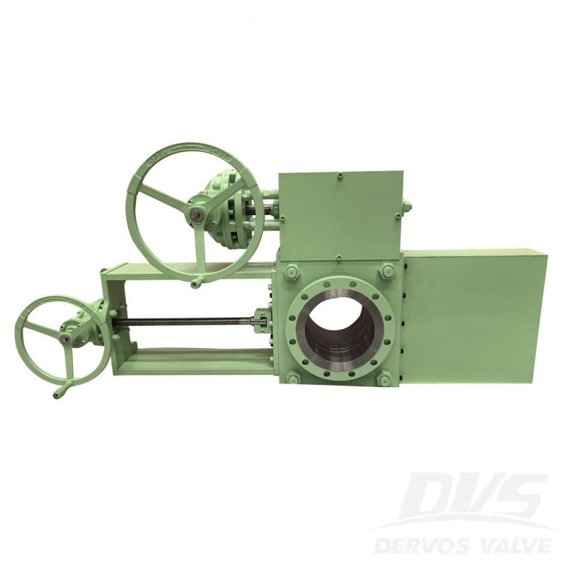
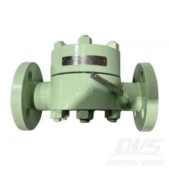
10-дюймовый линейный глухой клапан 150 фунтов изготовлен в соответствии со стандартом ASME B16.34. Корпус клапана изготовлен из A105. Он имеет противокапельные структурные характеристики. Его режим подключения - RF. И он имеет режим работы турбины.
Оплата:
30% when order confirmed, 70% before shipmentпроисхождение продукта:
ChinaЦвет:
Customizationпорт доставки:
Shanghai, ChinaВремя упреждения:
30~60 days Ex Works after order confirmationMaterial:
A105Method of Operation:
Turbine Operation
|
Тип |
Линейный глухой клапан |
|
Размер |
10" |
|
Давление |
150 фунтов |
|
Соединение |
РФ |
|
Эксплуатация |
Работа турбины |
|
Материал корпуса |
А105 |
|
Проектная норма |
АСМЕ Б16.34 |
|
Размер лицом к лицу |
Стандарт производителя |
|
Размер фланца |
АСМЕ Б16.5 |
|
Код испытаний и проверок |
API 598 |
|
Температура |
-29 ~ 150°С |
|
Применимый носитель |
Вода, нефть и газ |
1. Оснащен функцией быстрого открытия и закрытия, не требуется дополнительная разборка или установка трубопроводной арматуры, что сокращает время работы и нагрузку на рабочих;
2. Подходит для различных сред, включая газы, жидкости, суспензии и твердые частицы, широко используемые в таких отраслях, как нефтехимия, металлургия и энергетика.


Если вы заинтересованы в наших продуктах и хотите знать больше деталей,пожалуйста, оставьте здесь сообщение,мы ответим вам как только мы можем.
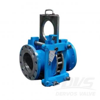
Линейный глухой клапан (очковый клапан) представляет собой разновидность задвижки, перекрывающей газовую среду вручную, электрически, пневматически или гидравлически. Обычно он делится на электрический глухой клапан, гидравлический глухой клапан, закрытый пробковый клапан и электрический открытый глухой клапан.
Линейные заглушки применяются в трубопроводных системах, когда необходимо либо полное перекрытие, либо беспрепятственный переход потока без значительного падения давления. THD (конструкция сквозного отверстия) обеспечивает быструю и плавную регулировку положения. Вариант THD-slide имеет конфигурацию с несколькими болтами, что упрощает эксплуатацию и уменьшает габаритную длину. Наличие дополнительных болтов корпуса делает этот тип особенно подходящим для применений с высоким давлением.

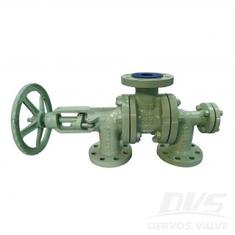
Задвижка DN400 PN40 изготовлена в соответствии со стандартом EN12516-1/2. Корпус клапана изготовлен из стали LF2. Клапан предназначен для работы с паром при рабочей температуре 250°C, рабочем давлении 1,3 МПа, расчетном давлении 2 МПа, диапазоне расчетных температур от -39°C до +350°C и диапазоне температур окружающей среды от -39°C до +34,7°C. Тип соединения – RF. Имеет редуктор. режим работы. Параметры продукта Тип Задвижка Размер ДН400 Давление ПН40 Связь РЧ Операция МЕХАНИЗМ Материал тела A182 LF2 Стандарт проектирования EN12516-1/2 Лицом к лицу Стандарты поставщиков Размеры фланца ГОСТ 33259-Тип B Кодекс испытаний и контроля EN12266-1/2 Температура -29 ~ 120 °С Применимый носитель Вода, нефть и газ Функции 1. Цельнокованая конструкция обеспечивает высокую структурную целостность и герметичность при давлении PN40. 2. Механизм скользящей заглушки с фланцем RF обеспечивает безопасную и эффективную изоляцию участков трубопровода. Технический чертеж Проверка размеров Испытание под давлением Рисование Табличка и упаковка Отчет об инспекции

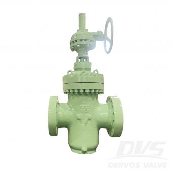
Запорный клапан-слайдер 10 дюймов, 150 фунтов, изготовлен в соответствии со стандартом ASME B16.34. Корпус клапана изготовлен из стали A105. Он имеет конструкцию, предотвращающую каплеобразование. Способ соединения – RF. Имеет турбинную конструкцию. режим работы. Параметры продукта Тип Задвижка Размер 10 дюймов Давление 150 фунтов Связь РЧ Операция Турбина Материал тела А105 Стандарт проектирования ASME B16.34 Лицом к лицу Стандарт производителя Размеры фланца ASME B16.5 Кодекс испытаний и контроля API 598 Температура -29 ~ 150 °С Применимый носитель Вода, нефть и газ Функции 1. Турбинный скользящий механизм обеспечивает плавную и эффективную работу при изоляции трубопроводов большого диаметра. 2. Корпус из кованой углеродистой стали A105 с фланцем RF обеспечивает прочность, долговечность и надежную герметизацию. Технический чертеж Проверка размеров Испытание под давлением Рисование Табличка и упаковка Отчет об инспекции
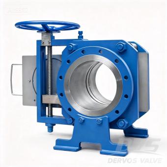
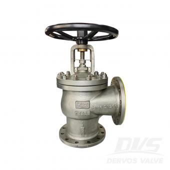
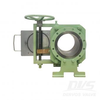
Введение Этот 10-дюймовый скользящий запорный клапан класса 300 обеспечивает абсолютную надежную изоляцию трубопроводов среднего и высокого давления, сочетая в себе надежность прочного физического барьера с простотой ручного винтового привода. В отличие от обычных клапанов, в которых используются подверженные износу седла, механизм скользящей заглушки создает настоящий физический барьер, обеспечивая нулевую утечку во время технического обслуживания без необходимости сброса давления в системе. Это значительно сокращает время простоя и повышает безопасность персонала. Конструкция с ручным винтовым приводом обеспечивает точное и контролируемое перемещение заглушки, а также обладает встроенной функцией самоблокировки для удержания положения под давлением — идеально подходит для применений, где электрический или пневматический привод может быть недоступен или нежелателен. Изготовленный в соответствии со стандартом ASME B16.34 с фланцами RF согласно ASME B16.5, этот клапан доступен в вариантах из кованой углеродистой стали (A105), нержавеющей стали или легированных материалов в зависимости от условий эксплуатации. Каждое изделие проходит 100% испытание под давлением в соответствии со стандартом API 598. Эта 10-дюймовая конфигурация класса 300 является популярным выбором для паровых, нефтяных, газовых и химических трубопроводов. Другие размеры от 1 до 60 дюймов и классы давления до класса 2500 доступны в рамках нашей полной линейки заглушек. Вырез для слайда THD Функции 1. Ручной винтовой механизм с самоблокировкой. Прецизионный винтовой привод обеспечивает плавное и контролируемое позиционирование глухой пластины. Самоблокирующийся механизм удерживает положение под давлением без дополнительных тормозных устройств. 2. Абсолютная физическая изоляция Сплошная глухая пластина создает настоящий барьер, обеспечивая нулевую утечку во время технического обслуживания — в отличие от клапанов, зависящих от седла, которые со временем могут изнашиваться или ухудшаться. 3. Работа в линию без сброса давления. Скользящий механизм позволяет переключаться между режимами подачи и заглушки без продувки системы, что сокращает время простоя и потери продукции. 4,10″ Класс 300 – Оптимальная балансировка Обладает более высокой пропускной способностью по давлению, чем класс 150, и при этом остается более экономичным, чем класс 600, что делает его универсальным выбором для широкого спектра промышленных применений. 5. Конструкция из кованой углеродистой стали. Кованый корпус из стали A105 обеспечивает высокую прочность, ударостойкость и надежную работу при термических циклах. 6. Проверено в соответствии со стандартом API 598. 100% гидростатические и пневматические испытания гарантируют герметичность перед отгрузкой. Стандартные технические характеристики Параметр Спецификация Тип Скользящий запорный клапан Размер 10″ (DN250) Номинальное давление Класс 300 (PN50) Связь Фланец RF, ASME B16.5 Операция Ручной винтовой привод (самоблокирующийся) Материал тела Кованая углеродистая сталь A105 (возможны другие сплавы) Материал уплотнения/седла Соединение металл-металл (нержавеющая сталь + графит) Стандарт проектирования ASME B16.34 Измерение «лицом к лицу» В соответствии со стандартом ASME B16.10 или стандартом производителя. Испытания и проверка API 598 (100% гидростатический и пневматический режимы) Диапазон температур от -29°C до +425°C (в зависимости от герметичности) Применимые медиа Пар, нефть, газ, вода, углеводороды Приложение Изоляция трубопроводов, нефтеперерабатывающие заводы, нефтехимические предприятия, электроэнергетика Технический чертеж Гибкие варианты дизайна Индивидуально разработанные конфигурации для требовательных приложений. Помимо базовой модели, этот заглушечный клапан может быть адаптирован для работы при высоких температурах, соответствия требованиям пожарной безопасности и обеспечения нулевого уровня выбросов (защиты от капель). Для установок, где пространство ограничено, доступен компактный вариант, обеспечивающий те же надежные характеристики изоляции при меньших габаритах. Упрощенное обслуживание уплотнений – Разборка не требуется Уплотнения интегрированы в защитную пластину, что позволяет операторам осматривать или заменять их без разборки клапана. Проверки состояния можно проводить во время эксплуатации клапана, до любого изменения его положения, обеспечивая проверку целостности уплотнения перед началом работы. Низкая общая стоимость владения Обтекаемая, прочная конструкция клапана обеспечивает надежное перекрытие потока с минимальным техническим обслуживанием. Уникальный механизм привода позволяет одному оператору быстро и безопасно перекрыть трубопровод — без использования инструментов — сокращая время работы и упрощая процедуры технического обслуживания. Параметры ●Удлинители маховика ●Блокирующее устройство ●Концевые выключатели ●Сливные/вентиляционные отверстия ●Защитные накладки на пластины для защиты уплотнений ●Компактная конструкция (фланцевое соединение с резьбой) ●Защита от дождя/пыли ●Ограничитель крутящ...


Авторское право © 2015-2026 DERVOS VALVE CO.,LTD.Все права защищены Блог / Карта сайта / XML / политика конфиденциальности