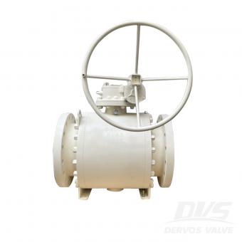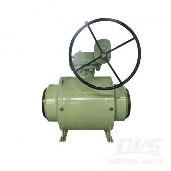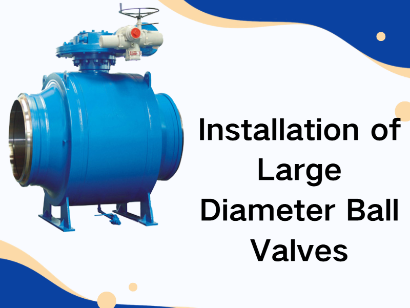
Large diameter ball valves are commonly used in industries such as petroleum and chemical processing, power generation, long-distance pipeline transportation, and large-scale water treatment systems. If installation is not performed correctly, it may lead to sealing leakage, valve jamming, or structural stress damage. Therefore, proper installation practices are essential to ensure long-term stable operation. 1. Pre-installation Inspection If pre-installation inspection is insufficient, operational failures are more likely to occur during service. First, inspect the valve body for transportation damage. If scratches, impact marks, or deformation are found on the valve body or sealing surfaces, installation should be stopped and the supplier should be contacted. Next, verify valve model, pressure rating, and connection standards. If the system design pressure does not match the valve pressure class, operational safety risks may occur. For example, if a low-pressure class valve is mistakenly used in a high-pressure pipeline system, the valve body may experience plastic deformation under water hammer impact. It is also necessary to check the condition of the ball surface and sealing rings. If there are scratches on the ball surface, sealing performance will be reduced. This is especially critical in gas transmission systems where micro-leakage is more likely. 2. Installation Direction Large diameter ball valves usually have a flow direction marking. If the installation direction is incorrect, the following problems may occur: If the fluid flow direction matches the design direction, the operating torque will remain more stable. If the valve is installed in reverse, the stem may experience increased mechanical load, which will accelerate stem wear during long-term operation. For double-seal bidirectional ball valves, although bidirectional flow is allowed, installation according to the marked flow direction is still recommended to ensure more uniform sealing stress distribution. In high-temperature or steam systems, if the installation direction is incorrect, thermal expansion may accelerate sealing ring aging. 3. Pipeline Stress Control Large diameter ball valves are heavy. If installed without proper support, additional bending moments may be transferred to flange connections. If pipeline systems experience axial displacement, pipeline supports should be installed for segmented fixation. If support structures are not provided, the valve body may bear long-term gravitational tensile load, eventually causing flange seal failure. It is generally recommended to install independent supports on both sides of large diameter ball valves. If the pipeline system is subject to thermal expansion and contraction, expansion compensation devices must be installed; otherwise, sealing surfaces may gradually fail. 4. Bolt Tightening Process Flange connections of large diameter ball valves usually ...

This year’s Dervos annual conference was noticeably more grand and well-organized than in previous years. In the morning session, each department delivered its annual work summary, reviewing key projects and achievements over the past year. Teams also openly shared the challenges encountered during implementation and the practical experience gained along the way. Through this cross-department exchange, everyone developed a clearer understanding of one another’s responsibilities and workflows, laying a stronger foundation for future collaboration and communication. In the afternoon session, the Outstanding Employee awards were presented. Each nominee shared their work achievements and practical experience, demonstrating a strong sense of responsibility and execution across different roles. It is precisely this proactive mindset, collaborative spirit, and down-to-earth working approach of Dervos employees that drives the team steadily toward its shared goals. Showing up on time every single day throughout the year — that’s quite an achievement. Ian has now received the Perfect Attendance Award for two consecutive years. During the annual conference, Dervos also presented medals and exclusive commemorative gifts to employees who have completed five years of service. Dervos values the long-term dedication and consistent commitment of its team members, and sincerely appreciates the trust and contributions they have made over the years. For many at Dervos, the company is not only a platform for professional growth, but also a stage where shared goals and collective efforts come to life. In the evening, the annual conference transitioned into the banquet segment. Performances and interactive games were seamlessly interspersed, creating a relaxed yet organized atmosphere. Laughter and cheers echoed throughout the venue, and in the moment the camera shutter clicked, the excitement and joy were captured in a single frame. Eric said: "Let’s dream together, DERVOS's dream. A dream where we all play a part, piece by piece, it becomes a reality." For Dervos, the annual meeting is not just about "summarizing the year," but about bringing our hearts together, strengthening our resolve in doing the same thing, and then continuing to move forward, step by step, with steady progress.
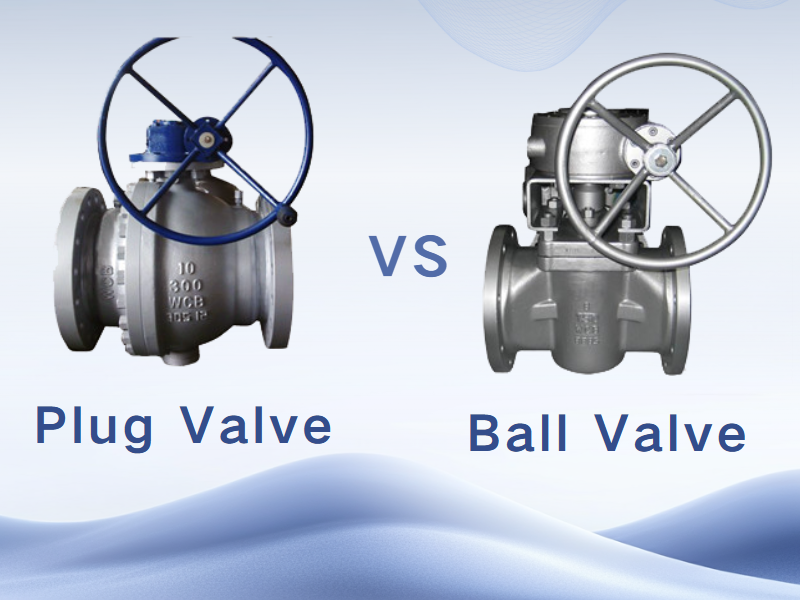
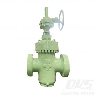
Ball valves and plug valves differ significantly in several aspects, including structure, operating principle, mode of operation, flow control capability, sealing performance, and application scenarios. These differences enable the two types of valves to perform distinct roles in their respective fields. Structural Differences The ball valve, a design evolved from the plug valve, utilizes a spherical element as its core component. By rotating the ball 90° around the stem axis, the valve can be opened or closed. Its structure is straightforward, consisting primarily of a spherical closure element with a through-bore housed within the valve body. In contrast, the structure of a plug valve is more complex. It comprises multiple components such as the valve body, bonnet, plug, seat, and stem. The closure element is a cylindrical or tapered plug that controls flow by rotating 90°, aligning or misaligning the port in the plug with the flow passage in the valve body to achieve opening or shutoff. Operating Principle The operating principle of a ball valve relies on the rotation of the ball to control the on-off flow of fluid. When the ball is in tight contact with the valve seat, the clearance between them is completely sealed, thereby preventing fluid leakage. When the ball rotates to a position disengaged from the seat, the fluid is allowed to flow freely through the passage inside the valve body. The operating principle of a plug valve differs in that it primarily controls the flow passage by rotating the plug element to open or close the valve. In a plug valve, the plug is connected to the stem and rotates together with it to achieve flow control. The closure element is a tapered plug with a port, and the flow passage is designed to be perpendicular to the axis of the plug. This configuration enables the plug valve to operate more efficiently and reliably during opening and closing. The operation of a ball valve is notably simple, requiring only a 90-degree rotation to achieve opening or closing. This design allows the flow passage to be opened or shut off quickly and smoothly when the ball is rotated by 90 degrees, providing both convenience and efficiency. In addition, ball valves offer relatively low flow resistance in the fully open or fully closed position, making them particularly suitable for applications that require rapid on-off operation. By contrast, the operation of a plug valve is comparatively more complex, as several turns are typically required to complete the opening or closing action. The valve plug is designed in a cylindrical or tapered form and regulates fluid flow through rotation. Nevertheless, plug valves demonstrate excellent performance in flow regulation, enabling precise adjustment of the flow passage diameter and accurate control of flow rate. However, due to the relatively complicated operating process, plug valves are not well suited for frequent operation...
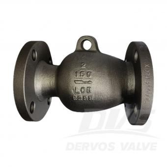

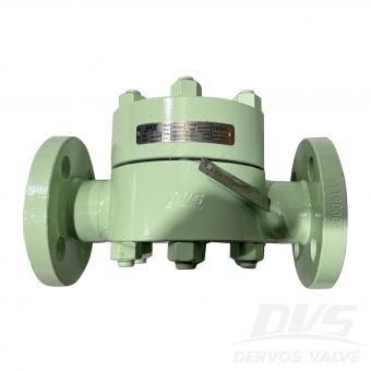
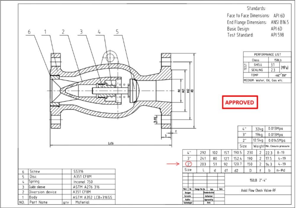
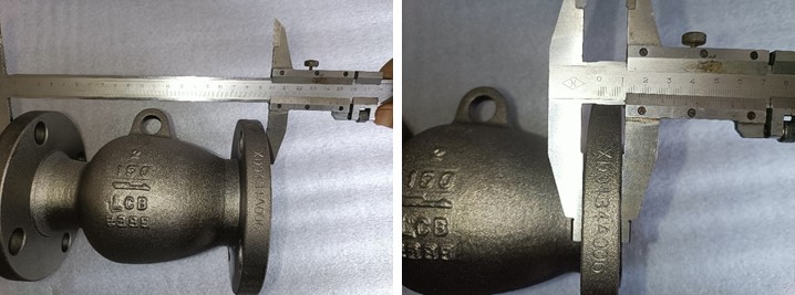
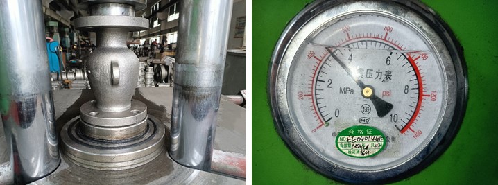
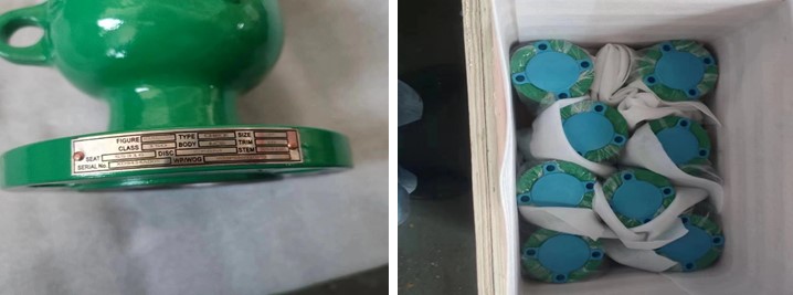
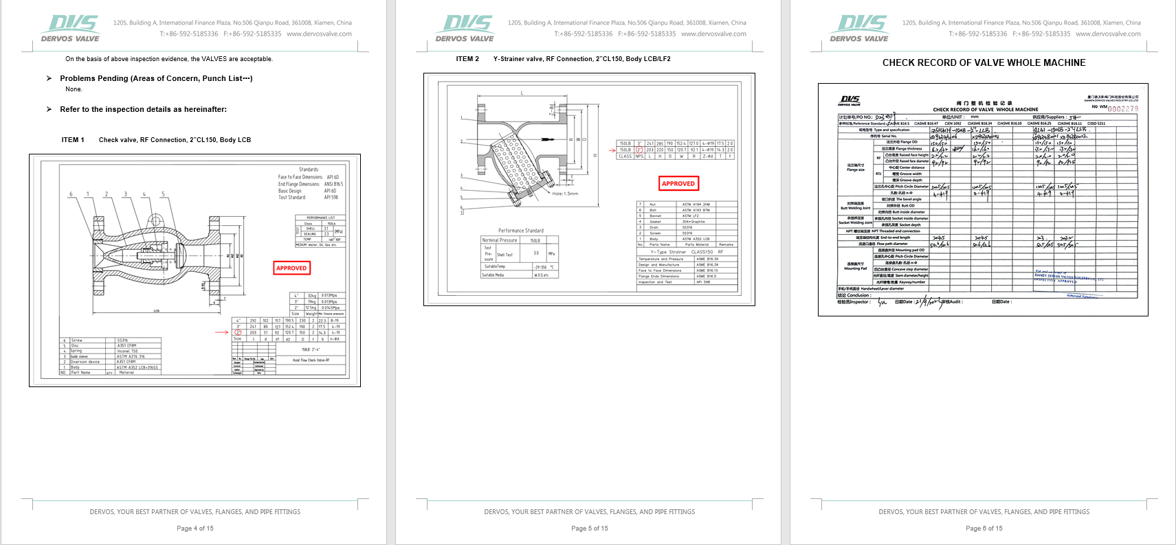
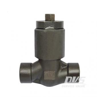
Осевой обратный клапан CL150 2” изготовлен в соответствии со стандартом API 6D. Корпус клапана изготовлен из стали ASTM A352 LCB+316SS. Он обладает конструктивными характеристиками осевого клапана. Тип присоединения – резьбовое соединение (RF).
Оплата:
30% when order confirmed, 70% before shipmentпроисхождение продукта:
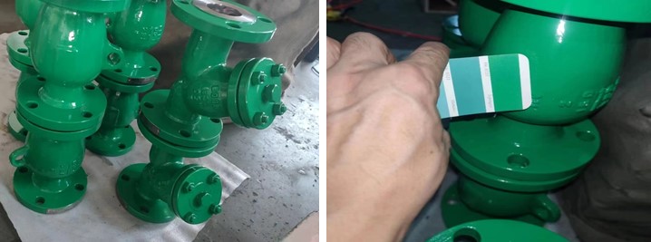
chinaЦвет:
Customizationпорт доставки:
Shanghai, ChinaВремя упреждения:
30~60 days Ex Works after order confirmationMaterial:
ASTM A352 LCB+316SSMethod of Operation:
H.W.
|
Тип |
Осевой обратный клапан |
|
Размер |
2” |
|
Давление |
CL150 |
|
Связь |
РФ |
|
Материал корпуса |
ASTM A352 LCB+316SS |
|
Норма дизайна |
API 6D |
|
Лицом к лицу |
API 6D |
|
Размеры концевого фланца |
ASME B16.5 |
|
Код испытаний и проверок |
API 598 |
|
Температура |
-46 ~ 350 ° С |
|
Применимая среда |
Вода, нефть и газ |
1. Конструкция с осевым потоком сводит к минимуму падение давления и обеспечивает плавный поток с низкой турбулентностью.
2. Изготовлены по стандарту API 6D с RF-концами, обеспечивают надежную предотвращение обратного потока в трубопроводных системах.
Если вы заинтересованы в наших продуктах и хотите знать больше деталей,пожалуйста, оставьте здесь сообщение,мы ответим вам как только мы можем.
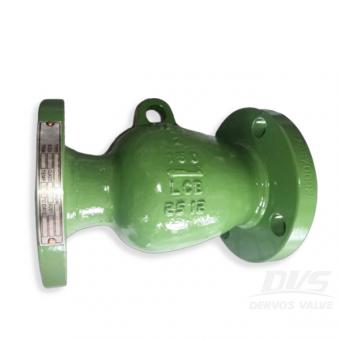
2 дюйма Освободный образец осевой форсунки является предпочтительным решением для предотвращения возврата или ударов на критический процесс оборудование. Спасибо за его LCB Тело, клапан способен для рабочей температуры до -46 Степень Цельсия.
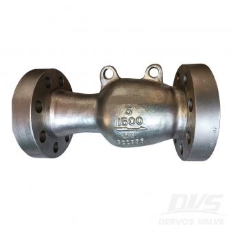
Обратный клапан с осевым потоком 3 дюйма, 1500 фунтов изготовлен в соответствии со стандартом API 6D. Корпус клапана изготовлен из A995 4A. Он имеет структурные характеристики типа осевого потока и структурную длину 473 мм. Режим подключения - RTJ.
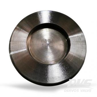
В однодисковый обратный клапан, изготовленный из CF8, имеет отличную стойкость к коррозии. разработан в соответствии с API594, клапан - вафельный типа.
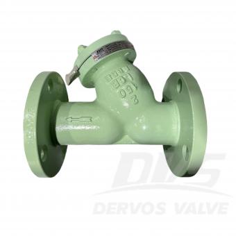
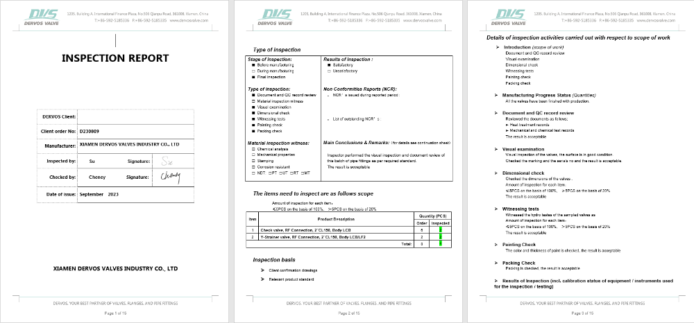
Y-образный фильтр 2 дюйма 150 фунтов сделано в соответствии с ASME B16.34 Стандарт. Корпус клапана изготовлен из ЛКБ . Он имеет структурные характеристики Y-образный, двойной экран, размер ячеек 1/16 дюйма, шаг отверстий 3/32 дюйма . Я т с с режим подключения является РФ .
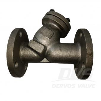
Фильтр типа Y диаметром 2 дюйма (150 фунтов) изготовлен в соответствии со стандартом ASME B16.34. Корпус клапана изготовлен из стали ASTM A352 LCB. Он имеет конструктивные характеристики BB, OS&Y. Тип соединения – RF.
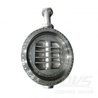
42-дюймовый дисковый затвор 150LBS изготовлен в соответствии со стандартом API 609. Корпус клапана изготовлен из CF8M. Он имеет конструктивные характеристики тройного эксцентрика, многоуровневого и NACE. Его тип соединения - фланец RF. И он имеет режим работы турбины.
Поставщик обратного клапана высокого давления в Китае предлагает Уплотнение давления CONNET CHART CHARD, ASTM A105N, 1 дюйм, класс 1500 LB, кованый стальной подъемник Проверить клапан.
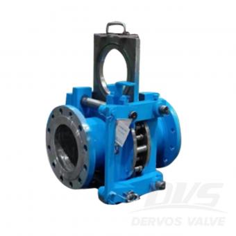
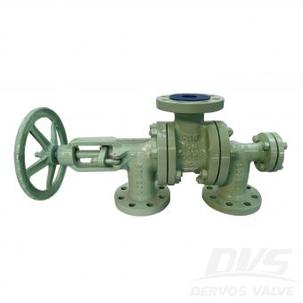
Линейный глухой клапан (очковый клапан) представляет собой разновидность задвижки, перекрывающей газовую среду вручную, электрически, пневматически или гидравлически. Обычно он делится на электрический глухой клапан, гидравлический глухой клапан, закрытый пробковый клапан и электрический открытый глухой клапан.
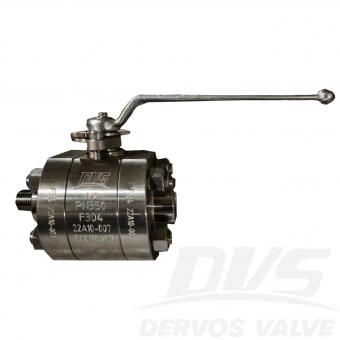
Шаровой поплавковый клапан 1/2” PN350 изготовлен в соответствии со стандартом ASME B16.34. Корпус клапана изготовлен из стали A182 F304. Тип соединения – резьбовое соединение M/F NPT. Клапан оснащен маховиком. operation mode. Product Parameters Type Floating Ball Valve Size 1/2” Pressure PN350 Connection NPT Operation Hand wheel Body Material A182 F304 Design Norm ASME B16.34 End to End MANUFACTURER STANDARD End connection NPT Test & Inspection Code ISO5208 Temperature -29 ~ 150 °C Applicable Medium Water, Oil and Gas Features 1.Three-piece floating ball valve structure allows easy disassembly for maintenance and in-line service. 2.F304 stainless steel body with PN350 rating and NPT ends ensures secure sealing under high-pressure conditions. Technical Drawing Dimension Checking Pressure Testing Nameplate & Packing Inspection Report
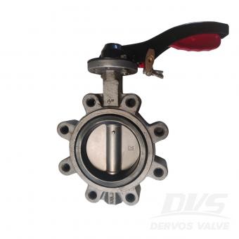
4-дюймовый дисковый затвор 150LB изготовлен в соответствии со стандартом API 609. Корпус клапана изготовлен из A216 WCB. Он имеет структурные характеристики центральной линии. Его тип соединения - проушина (резьбовое отверстие UNC, RF 125-250AARH). Рычажный (запорный) режим работы.

Затвор дисковый поворотный с тройным эксцентриситетом DN300 PN25 изготовлен в соответствии со стандартом EN 593. Корпус затвора изготовлен из WCB марки A216. Он имеет конструктивные характеристики: тройной эксцентриситет, многослойное уплотнение и монтажную длину 83 мм. Тип присоединения – LUG. Клапан имеет турбинный режим работы.


Авторское право © 2015-2026 DERVOS VALVE CO.,LTD.Все права защищены Блог / Карта сайта / XML / политика конфиденциальности